RA1792
Do you have a problem with your RA1792 LCD displays ? See below for some exciting news.
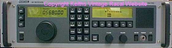
This is, I know, a very popular and sought after receiver , but how does it shape up to the earlier offerings from Racal..?
The first thing you notice is that the front panel layout is totally different from the RA17 and "12" series receivers. First of all there is no M/cs tuning knob, so this set tunes continuously from 0-30M/cs. Another thing you can't miss is the keypad..! The RA1792 allows you to manually enter the desired frequency, and store up to 100 channels of interest into its memory.These memories may be scanned,with user selectable dwell, in banks of 10.
The FREQ button is keyed first and then you key in the desired frequency and then key ENTER,simple.To be able to tune away from this frequency you must press the TUNE key.Another feature is the ability to look through the memory channels,and be able to select the one you require while still listening to the frequency you are tuned to.You can also scan up to 10 of these memory channels.
There are three AGC settings, plus manual, up to six bandwidth settings and 5 different modes.
Everything you need to know is displayed on the two LCD displays.
You may find this set with a number of options fitted.The one of most use to us enthusiasts is probably the SCORE interface, whereby you can control the radio via your PC. Don't ask me where you can get software for this as I don't know. There was someone advertising software a few years back but that is all I know.
So how good is the RA1792..? Certainly the set is a joy to use, the keypad is positive and , in my opinion, Racal have got the tuning rate for the "spin knob" spot on and the Passband Tuning is a nice feature. However , despite Racal's sales literature the RF performance of this set can only be classed as adequate, it is nowhere near as good as the RA17 or RA1772 for example. The RF Amplifier has no tuning or preselector circuits and if the set is connected to anything approaching a decent aerial then the receiver starts to overload.The fact that Racal have allowed for the amplifier stage to be linked out , so that the first mixer receives about 10db or so , less gain, hints at problems. Certainly the 1792 does not like to be connected to the MA1970 ( which has slight gain) when the amplifier is linked in. Racal made a number of Pre-Selector units for use with this set ,MA1101,MA1102 etc. I have spoken to a number of people who have used the 1792 in "anger" as it were, and it was not at the top of their list as a favorite. However that said, it is much better than any of the "12" series sets I have used by a very long way.
General Pictures.
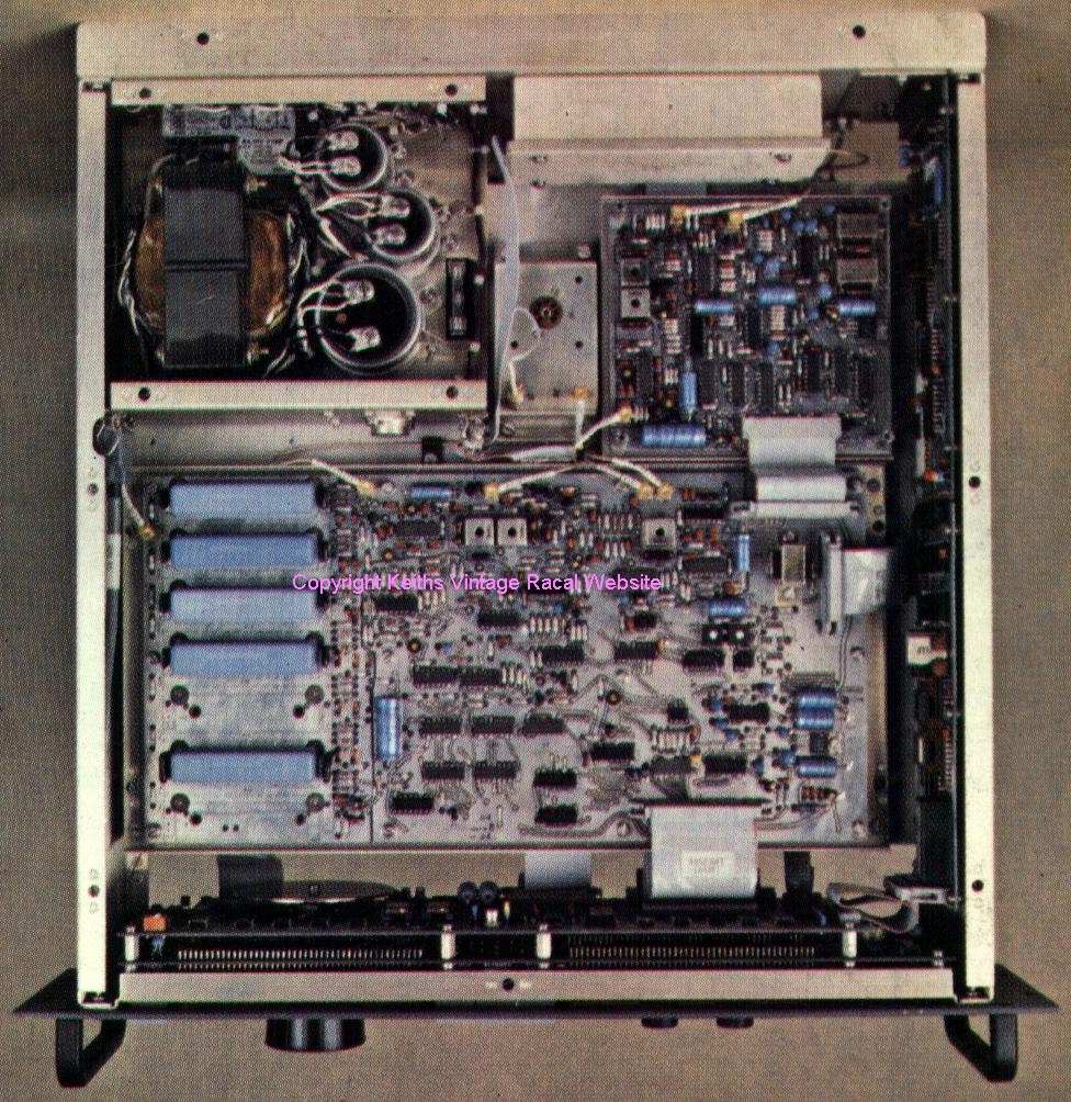
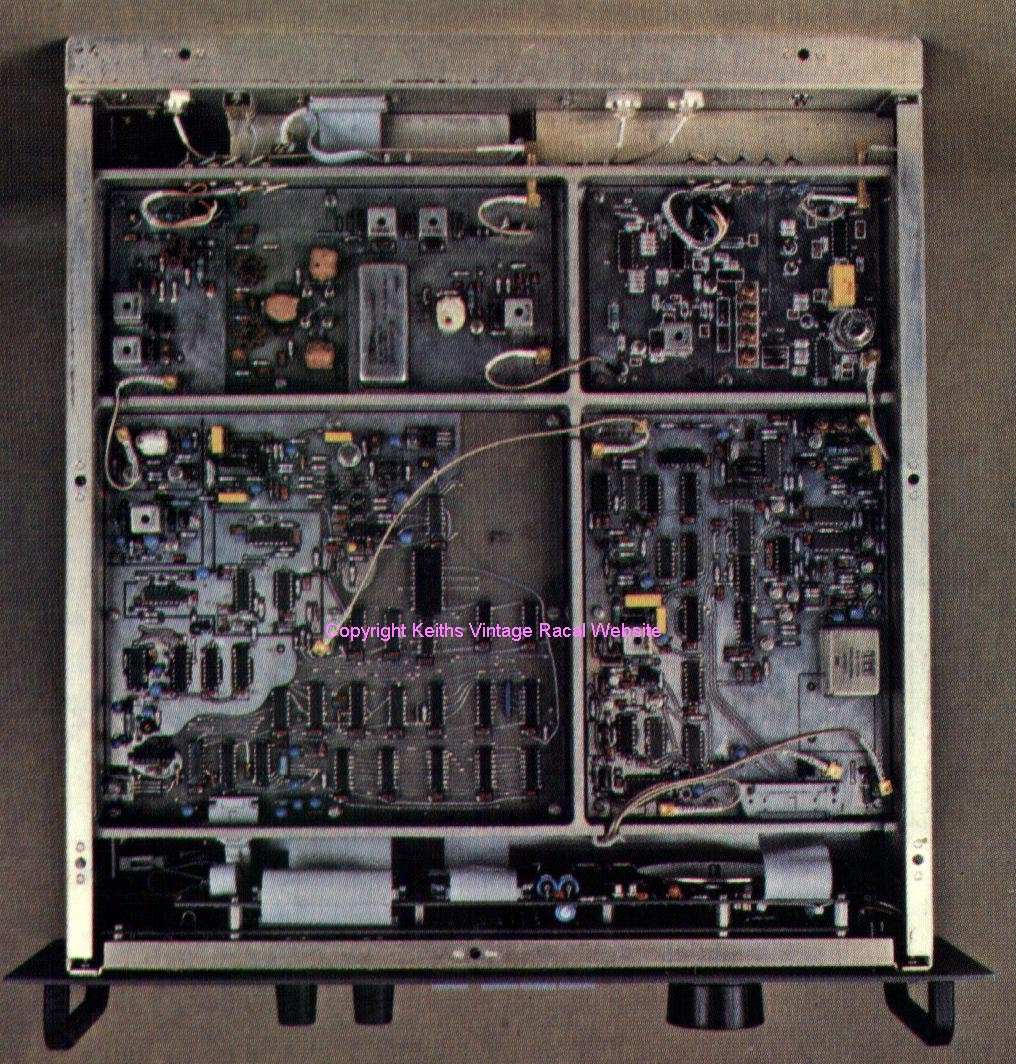
To the right the RA1792 viewed from above, and to the left the view from below with the screening covers removed.
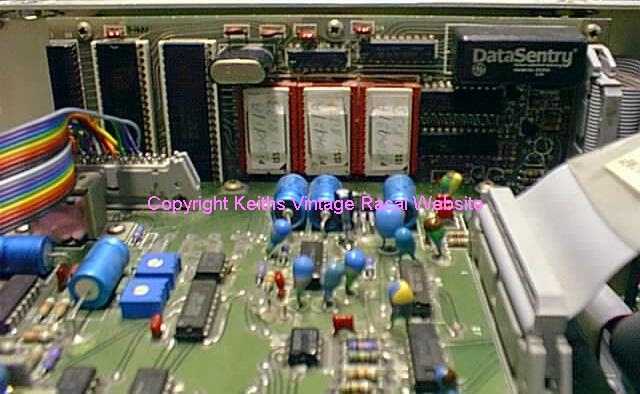
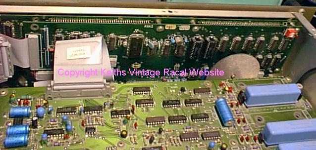
This shot left, shows the rear of the memory/display boards.To the right the troublesome CPU board.
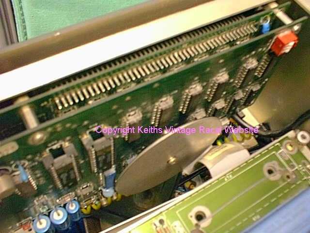
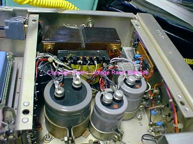
Here , to the left, is a closer view of the tuning encoder disc. To the right we have the Power Supply Unit.
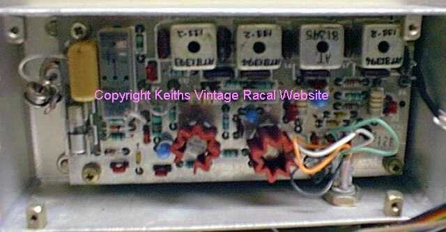
This is the RF Amplifier.
I should add that the couloured ribbon cable seen visible in the CPU 'photo was only there during an experiment with an interface.This is not Racal's work..!
I have added some info from John Whitehouse who worked for RACAL and is well qualified to comment.
People rave about the Racal RA1792 this was just a cost competitive and cheap receiver designed at Racal's factory in Rockville Maryland USA for a US government contract.
The RA1792 only had a 10dB signal to noise ratio which was poor when compared to the much earlier RA1772 with has a 15dB signal to noise ratio. The best of these sets was the RA1778 and the later RA1779 these were still quoted as 15dB signal to noise ratio but did not leave the factory with less than 17dB the last ones around 21dB which were the first semiconductor sets to equal the RA17 from 20 years before in signal to noise ratio, however as the RA17 had a tuned front end and these semiconductor sets did not (the majoritory had a optional tuned front end filter) the RA17 could still out perform the 1770 series of receivers. The same receiver modules where used in the remote control series of receivers the RA1784 being the most common the RA1781 is available on the surplus market but this was a special for GCHQ and had no revertive receiver data.RA1792's are well known for their problem processor boards, LCD displays and Thomson tantalum capacitors failing.
The processor board problem just never seemed to get solved. The early ones the back up battery leaked and corroded the board through. The next board the processor went obsolescent and RACAL had the final build so no second source of components. The later processor board (as did them all) had problems with corrosion around the plated through holes. All the above require a replacement board to repair. I can believe 2500 pounds for a replacement as Racal can charge what it likes as their military based spares organization guarantees spares for 10 years after the product goes out of production. The price is not guaranteed and Racal will charge what it can especially if it is the board with an obsolete processor. The spares will only become cheap when Racal dumps its spares holding when the product has been out of production 12 to 15 years, however in the case of the RA1792 it is still made today in India (where the spares will originate) so do not hold your breath for early and cheap spares availability except from customers disposing of their receivers and spares holdings. I think most of the UK and US customers have already disposed of their holdings this has made no noticeable market impact because the quantity in use was small when compared to the RA17. The RA1792 was sold in huge quantities overseas and it is there where spares may come from in the future. As stated before this particular Racal receiver is best avoided except if it is very cheap and working.
My Thanks to John for this info.
Brief Technical details.
| Frequency Range. | 15khz-30mhz |
| Mode | usb/lsb-am-cw-fm(isb optional) |
| Bandwidths | 300hz-1khz-3khz-6khz-16-khz |
| AF Outputs | 10mw-600ohm.1mw-600ohm.200mw int ls.200 mw 16 ohm ext ls.400mw 8ohm ext ls |
| IF Output | 455khz at 100mv into 50 ohm |
| AGC | short,medium,long,manual |
Good Points.
Very easy to use,no preselector to tune,no M/cs to select, just enter the frequency , select the memory , or spin the knob.Mode,AGC and bandwidth can be set to the default setting of your choice.
Easy to view LCD display enables you to see the receiver settings at a glance and tune to the exact frequency you want.
The receive sections are pretty straight forward and should present little problems to anyone who can repair ,say, an RA17. Basic alignment is straight forward. The power supply unit is just about as basic as you can get,nothing switched mode here.
The RF input to the set is well protected. It will stand a continuous signal of 50 Volts E.M.F without damage. There is a fuse and a spark gap fitted for protection against higher voltages.
It is a lovely set to own and use.
Bad Points.
Look out for damaged or worn out LCD displays, they can be, and are often a problem. The microcomputer board suffers its fair share of problems.The memory backup battery can leak, damaging the circuit board, and there are corrosion problems with the board and there are also problems with dry joints.There were a number of different processor boards and they may not be compatible with SCORE or GPIB boards if you have these fitted.The tuning encoder can sometimes fail,and the tantalum capacitors on the set dry out , Racal engineers often just replaced all of them rather than spend time trying to find a faulty one. Fault finding on the control side of the set can be a nightmare, OK if you are a competent engineer but if you are just a "user" then you will have problems. Another problem is parts.The set is full of what were once common I.C's but today, trying to locate, say, the 3850 CPU.. well good luck..! They are available but you really have to search and the companies that stock them often only supply the trade.
Help is at hand for those that have bad displays on
their RA1792
Take a look here http://www.1792lcd.com/index.php?sect=fdisplay
I have yet to try any of these displays but they certainly look good and it may
be possible to use the Frequency Display on the RA1723 Drive unit.
Despite moronic comments made in a magazine about Johns information above, what
he has written is true.Who will you believe, someone who worked for Racal and
was involved with the set or someone who has one for a short while, sticks a
couple of signals in to check RX performance, and pronounces a verdict on the
set ? The RA1792 is cheaply constructed.This set is not as well made as other
models,even the screening covers only rely on the "spring" in the
fingers to keep them in place,unlike the RA17/RA1217 where they are also held
in position by screws. The tuning encoder is not enclosed as it is in the
RA1772 and the "bearing" if it can be called that, is just a nylon
bush. There is no screening of the IF Board or Processor Units. I now have
details on five different CPU board types and if anyone tells you faults are
just down to loose connections or poorly seated chips then they are a clown.
Sitting in front of me now is a CPU board where every chip , with the exception
of U1, U3 ,U5 (74LS10 , 74LS02 , 74LS04) is faulty. This is going to be an
expensive repair. The owner was just sitting there tuning away when the set
just displayed " All Zero's" and gave up.The only good thing about
this one is that all of the IC's are in holders. I just hope the SCORE card is
ok.
Later CPU boards have a simple go/no go indication fitted by way of two LED's. A three way DPI switch is used to select the "Test". I find it quite amazing that we get fairy tales about Racal and "known problems" with the RA17's AGC but where there were problems , as indicated by the many different CPU boards made , this is not even mentioned. I suppose ignorance is bliss. John Whitehouse mentions that the CPU problems was never properly sorted and experience supports this. I believe later model RA6790/GM's had the Mostek chip CPU Board replaced with a Z80 version.
I have more cries for help on the RA1792 than I do with any other set.
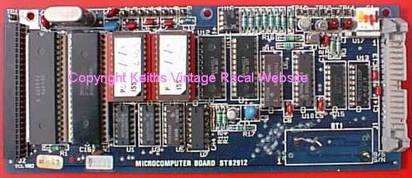
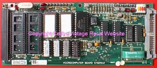
The pictures above show two of the various types of CPU board.They are both faulty. The one on the left is awaiting a new battery, as a precautionary measure , after the fitting of a new 3853 SMI chip.The board on the right has faulty chips in every position except the EPROMS and U1,U3,U5 the three silver coloured devices below the EPROMS
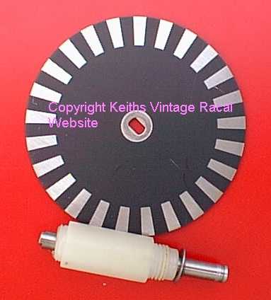
This picture above shows the Tuning Encoder disk and the "Bearing". A new bearing has had to be made as for some reason this one has sheared off. It looks like the original material used was Delrin but Nylon66 is suitable as a substitute.The bore was reamed out to 0.2505" diameter to give minimal clearance on the shaft and "Tri-Flon" was used as a lubricant.
Helps on Fault Location.
There is a group on Yahoo dedicated to the RA1792's cousin, the American
RA6790GM.
There are many similarities between the two sets and the group also shares info
on the RA1792 as well.
The link is http://groups.yahoo.com/group/Racal6790GM/
and well worth joining.
Some common problems.
I have found two main problems with the RA1792, CPU board failures and Tantalum Capacitor failures. One of the first things to do on the sign of a faulty Tantalum is to replace the lot. I know it is a lot of work but for some reason, on the RA1792 , they seem to be more prone to failure than the earlier RA1772.A bit of care is needed as they can be quite stubborn sometimes and refuse to budge.Check the supply lines as quite often a tantalum can bring these down indicating a fault elsewhere on the set. A set with an apparently dead CPU board only turned out to be a supply line failure.
Another problem that can crop up from time to time is that of corrupted memory data.This is usually down to the ER3400 EAROM's fitted to the A9A2 board, they either fail or have a supply problem. Check the -12v supply from U11 and the -30v supply which is generated on the board.
If your RA1792 starts to lack sensitivity or sounds like it may be "Cross Modulating" check the 1st Mixer.
RA1792's do not like getting hot.Some sets do seem quite tolerant of heat but the RA1792 is not one of them, not at the age they are now, anyway. Allow plenty of air to circulate around the set and if you use one in a cabinet remove the top and bottom covers.A friend of mine ,who has had extensive experience with the RA1792, and still serves in the forces, suggests fitting a small fan at the rear of any enclosure where the RA1792 is used. Indeed the last time I visited him he showed me how he had implemented a fan on the rear of the type of cabinets that we both use for the 1792's.
Don't forget to use Anti-Static Precautions, otherwise you may end up with more problems than you started with.
Filters.
It is worth commenting a little on filters.
There are some 1792 versions that have just one symmetrical 3.2 kHz filter and shift both the 1st LO and the BFO up or down the same amount to give LSB or USB, without apparent tuning shift. It saves the cost of one filter. The ISB versions have the full 6 filter set. No 1st LO shift here, and the BFO stays at the notional 455 kHz carrier frequency.
'GA' filters are offset, 'GB' filters are normal.It also appears that you need the correct firmware on the CPU board for either the 'GA' or 'GB' version.
BITE
The first thing I should comment on here is that not all RA1792's are equal and there are many different options. Not all sets have BITE and not all sets have full BITE. I am going through the process of tying up "program" numbers to find out what does just what. Please bear in mind what follows may not be applicable to your set . I will post software details here when I have collated enough info.
To invoke the BITE sequence set S1B on the A9A2 board ( front panel) to "Closed" , "Remote" should start flashing in the left hand display..
Press "Remote" followed by "00". this will start the BITE sequence from the beginning. The microprocessor will step through each test and will stop on any that fail. The number of the failed test is displayed in the "Channel Number" display. The test can be re started by pressing "Remote" and the next two digits of the sequence.When the test sequence is finished then all segments of the displays will be turned on.
Obviously you need a working CPU board before you can proceed with BITE.
Table indicating CPU switch tests.On compatible boards ONLY.
| Switch Position | D1 | D2 | |
| 1111 | On | On | Normal Operation |
| 0111 | Flashing | Flashing | Rom Signature Analysis |
| 1011 | On | Flashing | I/O Exercise |
| 0011 | Flashing | Off | DAC Ramptests |
| Any Other | Flashing | On | Bite Continuous Update Mode |
If you find a fault with the CPU then you will have to cure this before progressing.
Now... what happens when you start the BITE sequence seems to vary as to what software version you have fitted.
Here is one version.
| Failed Test Number | Reason for Failure |
| 10 | 20Mhz Reference osc out of lock |
| 11 | BFO out of lock at -8khz |
| 12 | BFO out of lock at +8khz |
| 20 | USB audio level in AGC out of range |
| 21 | USB AGC/MGC variation greater than +-2db |
| 22 | Insufficient I.F Isolation with no filter selected |
| 25 | LSB audio level in AGC out of range |
| 26 | LSB AGC/MGC variation greater than +-2db |
| 31 | FL3 More than 6 db below other filters |
| 32 | FL4 More than 6 db below other filters |
| 34 | FL6 More than 6 db below other filters |
| 35 | FL7 More than 6 db below other filters |
| 36 | Insufficient DAC range to adjust Audio to required level |
Here is another version of the table above.
| Failed Test Number | Appropriate Procedure |
| 10 | Second LO out of lock |
| 11,12 | BFO out of lock |
| 20,21,22 | Low gain or low sensitivity |
| 25,26 | LSB/ISB low gain or low sensitivity |
| 31,32,33,34,35 | Poor bandpass response |
| 50 | Faulty display on LCD panels |
Now , as I mentioned above not all RA1792's are equal and the following notes apply.
P80960 Iss 2 Test 35 is not used and the result of test 33 should be ignored.
Test 33 is not carried out for sets with GA options.
The following info applies to RA1792 type 83000, 82129 and 85830. On sets fitted with IEE-488 Test 30 seems to be for this module.
| Test Number | Details | Failure |
| 0 | PSU +5V line voltage | 'H' or 'L' plus measured voltage is shown in frequency display |
| 1 | PSU +12V line voltage | As above. |
| 2 | PSU +20V line voltage | As above. |
| 3 | PSU +15V line voltage | As above. |
| 4 | PSU -15V line voltage | As above. |
| 5 | PSU -305V line voltage | As above. |
| 6 | PSU -12V line voltage | As above. |
| 7 | Display test All display segments switched on and off. | Visually check display and note any failed segments |
| 8 | Rom sumcheck | Faulty sumcheck figure |
| 9 | Non destructive RAM test | Number of faulty IC shown. |
| 10 | Non destructive EARROM test | Number of faulty IC shown. |
| 11 | Reference oscillator varactor line voltage | |
| 12 | BFO varactor line voltage | Test number plus "Fault" indicator |
| 13 | L.O synthesizer varactor and voltage sweep test | Test number plus "Fault" indicator |
| 14 | A3 AGC line voltage test | Test number plus "Fault" indicator |
| 15 | BFO sweep test | Test number plus "Fault" indicator |
| MAIN I.F AGC/MGC COMPATIBILITY TESTS | ||
| 16 | Initial audio level out of range | Test number plus "Fault" indicator |
| 17 | Audio level after gain change out of range | Test number plus "Fault" indicator |
| 18 | Insufficient isolation by filters | Test number plus "Fault" indicator |
| ISB IF AGC/MGC COMPATIBILITY TESTS | ||
| 19 | Initial audio level out of range | Test number plus "Fault" indicator |
| 20 | Audio level after gain change out of range | Test number plus "Fault" indicator |
| 21 | Filter insertion loss -Filter 1 | Test number plus "Fault" indicator |
| 22 | Filter insertion loss -Filter 2 | Test number plus "Fault" indicator |
| 23 | Filter insertion loss -Filter 3 (GB option only) | Test number plus "Fault" indicator |
| 24 | Filter insertion loss -Filter 4 | Test number plus "Fault" indicator |
| 25 | Filter insertion loss -Filter 5 | Test number plus "Fault" indicator |
| 26 | General fault -all filters low | Test number plus "Fault" indicator |
| 27 | AM detector test | Test number plus "Fault" indicator |
| 28 | FM detector test | Test number plus "Fault" indicator |
| 29 | Flashes 30 as next test. This is a prompt to connect a loop back connector if SCORE is fitted | |
| SCORE Loop back tests | ||
| 30 | Score user function port faulty | 01 Shown on display |
| 31 | Transmit interrupts faulty | 02 Shown on display |
| 32 | Receive interrupts faulty | 04 Shown on display |
| 33 | Received data incorrect | 08 Shown on display |
The following info is for software versions.P805060 , P805061, P805062, P805063 IEEE-488 GPIB/HPIB compatible.
| Test Number | Details |
| 00 | +5V PSU voltage test. |
| 01 | +12V PSU voltage test. |
| 02 | +20V PSU voltage test. |
| 03 | +15V PSU voltage test. |
| 04 | -15V PSU voltage test. |
| 05 | -30V PSU voltage test. |
| 06 | -12V PSU voltage test. |
| 07 | Display test |
| 08 | ROM sumcheck |
| 09 | Non destructive RAM test |
| 10 | Non destructive EAROM test |
| 11 | Reference oscillator varactor line voltage test |
| 12 | BFO varactor line voltage test |
| 13 | 1st LO varactor line voltage test, sweep test 1mhz steps,20khz steps. |
| 14 | 1st IF (A3 module) AGC line voltage test. |
| 15 | BFO sweep test |
| 16 | Main IF AGC/MGC compatibility |
| 17 | Measures AGC line voltage |
| 18 | Increases manual gain voltage by 2.5 v (60db) |
| 19 | ISB IF AGC/MGC compatibility |
| 20 | ISB IF AGC/MGC compatibility |
| 21 | Measures audio level via FL3 |
| 22,25 | As above for FL4,5,6,7 |
| 26 | Compares max level from test 21-25 and checks remaining 4 filters |
| 27 | AM detector test |
| 28 | FM detector test |
| 30 | Displays IEEE interface address. |
Of course what you do about any fault you may find is another matter.Signature analysis would be the next step and depending on what manual you have varying levels of info are provided on this. Not all firmware versions are suitable for Signature Analysis however.
If there is enought interest I will include a section on Signature Analysis on this site at some stage.
Signal levels.
| Test Point | Relative signal level | Signal Level RMS. |
| A1J1 | 0db | 0.5uv |
| J5 | -1db | 0.46uv |
| E9 | -10db | 0.16uv @40.455Mhz |
| At A3E1 | +4db | 0.8uv @40.455Mhz |
| TP1 | +18db | 4.0uv @40.455Mhz |
| TP2 | +24db | 7.9uv @40.455Mhz |
| TP3 | +37db | 35uv @ 455Khz |
| U4 Pin 14 | +35db | 25uv @ 455Khz |
| At A3E3 | +55db | 280uv @ 455Khz |
| TP1 | +42db | 63uv @ 455Khz |
| TP7 | +116db | 300mv @ 455Khz |
| U28 Pin 7 | 350mv @ Audio |
All signal levels are relative to the input at the antenna and should be measured with an RF or AF Voltmeter , as appropriate, using a high impedance probe.AGC Off and IF Gain set to Maximum.
| 1st LO 40-70.455 | +13dbm into 50 ohm |
| BFO 455khz | 100mv RMS into hi impedance |
| IF out 100 mv RMS | 100 mv RMS |
I hope this page has helped to provide a bit more information on the RA1792. If you get a problem with your RA1792 you can always contact me for help and I'll do my best , I have many contacts around the world who have experience on the set. I can't promise that we will cure the fault, but what I can promise you is that you won't get some idiot looking down his nose at you, sneering , just because you have been unlucky enough to own a faulty set. Something these "experts" never seem to suffer from or at least never admit it.
03/06/2001
Updated 03/05/2002